Designing the Robot
Drive System
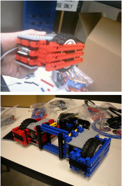
When the contest began, team 27 had only two members, Kevin and Tommy. We decided that the emphasis should be on mobility first, so while many teams began work on their lifting mechanisms, we worked on the basics. A differential drive with a gear ratio of 75:1 gave the robot enough torque but still allowed for very high speed. The first components we built were the gearbox/drive wheel assemblies, and they were fully independent of each other. They could simply snap off of the central chassis to make modifications easier in the future.
The central frame held the two wheel assemblies together and gave the whole chassis enough strength to survive the mandatory three foot drop test. Kevin, who had previous experience with caster wheels, added a central caster in the back to stabilize the robot.
The central frame held the two wheel assemblies together and gave the whole chassis enough strength to survive the mandatory three foot drop test. Kevin, who had previous experience with caster wheels, added a central caster in the back to stabilize the robot.
Lift Mechanism
With mobility taken care of, our attention soon shifted to the task of lifting tennis balls over the six inch rift. Around this time, Pranav joined the group. The first attempt at a lift mechanism was an assembly of large wheels at the front of the robot that would press the balls against the rift and then lift them upwards as they spun. This design proved to be inefficient and unreliable, so the idea was abandoned. Next, we tried another design using spinning wheels, this time to try to pull the balls up an incline to be stored at the top of the robot. The design worked well for tennis balls, but the spacing was an issue for lifting the bomb since the bomb was slightly smaller and much smoother than a tennis ball.
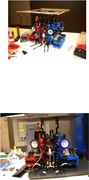
Finally, in a stroke of brilliance, Kevin had the idea for a servo-mounted arm to lift the balls upward, allowing them to roll back onto a pair of rails on top of the robot to store them. A switch mounted inside the lift arm would be pressed when a ball was in the correct position to be lifted. The design allowed for quick lifting and the ability to store up to three tennis balls, and the strong servo had no trouble lifting even the rift sealing bomb. With days of testing to determine the ideal shape for the lift arm and the "funnel" to position the balls, team 27 started to look pretty Xtreme indeed.
The final touches to the robot included a way to consistently drop the tennis balls over the rift when the robot was in position to score. A small arm attached to a servo accomplished this task, and slight modifications to the rails prevented balls from getting stuck. We added a pair of IR LED/Phototransistor breakbeams, one at the front of the rails and the other at the back. The front breakbeam was used to determine when a ball was actually picked up by the lift arm, and the one at the back ensured the balls had actually left the rails when the robot tried to score. Finally, and most importantly, the team wired up a pair of LEDs, one blue and one red, to be used for the robot's eyes. Because of the half-and-half nature of the robot's colors, the team decided to name him Arnold, after the half iced tea/half lemonade drink(and golfer) Arnold Palmer.
Electronics
Since the robot was to be autonomous, we had to incorporate input from the outside world into the robot. A variety of sensors were available, and in total there were 6 sensors used. The most important one for navigation was the gyro, which measured how far Arnold had turned from his starting orientation. Paired with a breakbeam encoder wheel to measure how far he had travelled, the gyro allowed Arnold to successfully navigate to any given point in the coordinate system of the board. Two switches were used, one at the front of the lift arm and another mounted on the encoder wheel in such a way as to detect if Arnold was lifted off the ground. This was important, because in testing he would often overshoot a ball and bring his arm down on top of a wall, lifting the drive wheels off of the ground and becoming hopelessly stuck. The final sensors used in the design were the breakbeams on the rails, mentioned earlier.
